Tensioning Device
Ensure Transmission Efficiency
Maintain appropriate tension: It can keep transmission components such as belts and chains under an appropriate tension force at all times, avoiding slipping. Take belt transmission as an example. If the belt is too loose, it will cause relative sliding between the belt and the pulley, reducing the transmission efficiency. However, the tensioning device can effectively prevent this situation and ensure that the power can be transmitted efficiently and stably.
Reduce energy consumption: By maintaining the good tension state of the transmission components, it can reduce the additional energy consumption caused by the looseness or vibration of the transmission components, and improve the energy utilization efficiency of the entire transmission system.
Extend Service Life
Even force distribution: It can make belts, chains, etc. be more evenly stressed during operation, preventing premature wear or fatigue damage caused by excessive local stress. For example, in chain transmission, the tensioning device can ensure that the stress between each chain link of the chain is balanced, reducing the wear and deformation of the chain links and extending the service life of the chain.
Reduce impact load: It can buffer the impact and vibration during the transmission process to a certain extent, reducing the instantaneous impact force on the transmission components, thereby reducing the risk of damage to the components caused by impact and extending their service life.
Improve Stability and Reliability
Prevent tooth skipping and chain derailment: In systems such as chain transmission and gear transmission, the tensioning device can effectively prevent faults such as chain tooth skipping or chain derailment. For example, in the chain transmission system of a bicycle, the tensioning device can ensure that the chain always maintains a good meshing state with the sprocket during riding, avoiding the situation of chain derailment and ensuring the stability and reliability of riding.
Adapt to different working conditions: Many tensioning devices have an automatic adjustment function, which can automatically adjust the tension force according to the operating status and load changes of the transmission system, adapt to different working conditions, and improve the stability and reliability of the system.
Convenient Maintenance and Adjustment
Easy installation and debugging: The structure of the tensioning device is generally relatively simple, and the installation and debugging process is relatively convenient. When installing a new transmission system or replacing transmission components, it can be installed and adjusted quickly and accurately, reducing the installation and maintenance time of the equipment.
Precise adjustment available: Operators can precisely adjust the tension force of the transmission components through the tensioning device according to actual needs, ensuring that the transmission system reaches the optimal working state.
Wide Application Range
Multiple transmission forms: The tensioning device can be widely applied to various transmission forms such as belt transmission, chain transmission, and rope transmission, meeting the transmission requirements of different industrial fields and mechanical equipment.
Different working environments: Whether in harsh working environments such as high temperature, low temperature, and humidity, or in complex working conditions such as dust and oil pollution, there are tensioning devices with corresponding materials and structures that can be applied to ensure the normal operation of the transmission system.
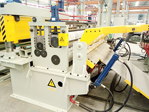
Swing Tensioning Device
Structural Composition: It includes an installation frame. On both sides of the top end of the installation frame, there are a first frame and a second frame. At the top ends of the two frames, there are installation seats. A transmission shaft is installed in the installation seats through bearings. At both ends of the middle part of the transmission shaft, swing arms are fixed. At one end of the swing arm away from the transmission shaft, there is a first shaft seat. A tensioning roller is installed between the first shaft seats through bearings. On the inner side of the bottom end of the first frame, there is a side frame, and on the outer side, there is a turnover frame. A fixing plate is installed between the two through a rotating shaft. In the middle of the inner side of the fixing plate, there is a cylinder. At the end of the output shaft of the cylinder, a shaft head is fixed. At the top end of the shaft head, a connecting rod is movably installed. On the outer side of the top end of the first frame, there is a shaft frame, and the shaft frame is connected to the connecting rod through a rotating shaft.
Working Principle: Start the cylinder. The cylinder lifts the shaft head. The shaft head drives the connecting rod to turn over along the shaft frame. The connecting rod drives the transmission shaft to rotate. The transmission shaft drives the swing arm to swing downward synchronously. The swing arm drives the tensioning roller to descend through the first shaft seat to pull the steel strip and increase the tension. When the cylinder drives the shaft head to retract, the tension is reduced, and the tension is kept stable during the conveying of the steel strip.
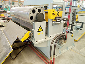
Pneumatic Tensioning Device
Structural Composition: It is mainly composed of a cylinder, a transmission roller, a tension sensor, a pneumatic control system, etc. The cylinder provides the tensioning power. The transmission roller is used for transporting the plate and realizing the tensioning function. The tension sensor monitors the tension of the plate in real time. The pneumatic control system includes a solenoid valve, a pneumatic controller, a pressure sensor, etc., which are used to control the air pressure to adjust the extension and retraction amount of the cylinder rod.
Working Principle: Utilize the compressibility and expandability of the gas. Control the air pressure in the cylinder through the pneumatic control system to change the extension and retraction amount of the cylinder rod, thereby adjusting the tension of the plate. A closed-loop control system is adopted. The tension sensor monitors the tension state of the plate in real time, and the control unit adjusts the air pressure in the cylinder according to the feedback signal to maintain the tension within the set range.
Tail Shaft Tightening Device of Plate Feeder
Structural Composition: It is composed of a driven shaft, two driven sprockets, bearings, bearing seats, tightening springs, tightening screws, etc. The sprockets are fixed on the shaft through keys. At both ends of the shaft, double-row self-aligning roller bearings and bearing seats are installed. The bearing seats are installed on both sides of the frame and can slide back and forth between the slide rails.
Working Principle: By adjusting the tightening screws, the tension of the chain is made uniform, and the horizontal position of the chain is tightened and adjusted to ensure that the chain is moderately tight and loose, so that it can run stably. When the chain plate is impacted by the material, the composite spring plays a buffering role to protect the chain plate and other components.